Tuesday 20 December 2016

11.9 Images In Curved Mirrors- Convex


11.9 Images in Curved Mirrors - Convex

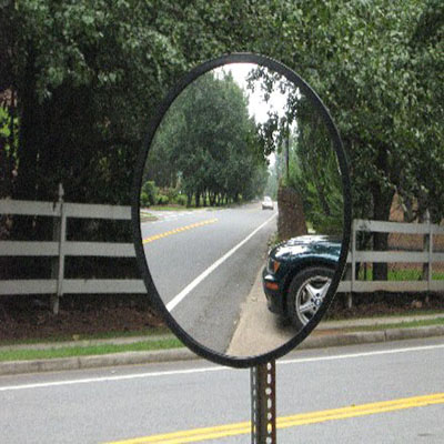
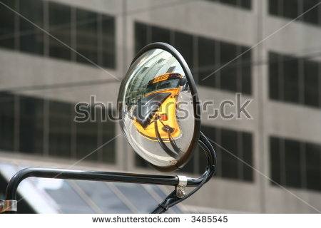
Convex mirrors (sometimes called Diverging mirrors) are opposite to concave mirrors. Convex mirrors display a smaller image, but shows more in total, which makes it useful in tight corners and situations(ex. Parking garages, stores and subways) when you need to see around a corner. Or can be used for reversing mirrors in cars/trucks so you can see all of your surroundings, instead of just the smashed grill of the Buick you just hit behind you.
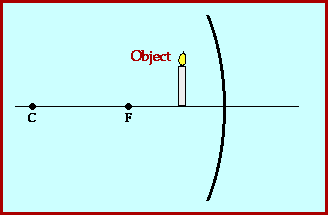
Convex mirrors always display a smaller, upright, virtual image.

Reflected rays off of a convex mirror always diverge, that's why its also called a Diverging Mirror.

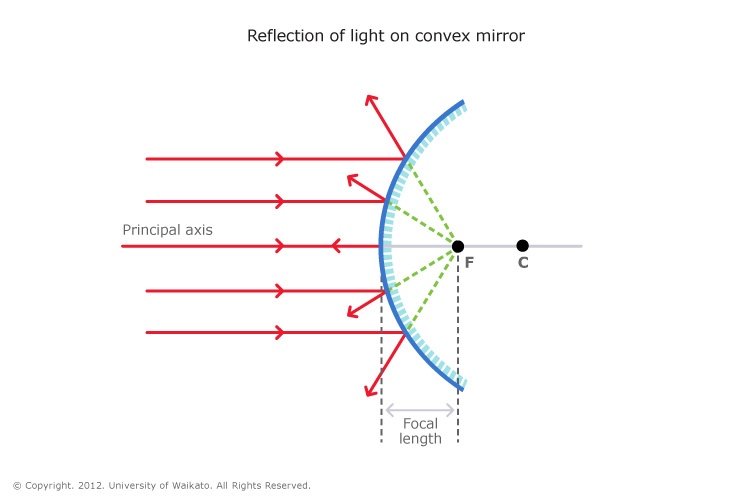
To locate the reflected image, continue the reflected rays behind the mirror, wherever those lines intersect, is where the image would appear.
Note: F is now called Virtual Focus.

Terminology:
Centre of Curvature: Centre of the sphere whose surface has been used to make the mirror.
Principal Axis: the line through the centre of curvature to the midpoint of the mirror.
Vertex: the point where the Principal Axis meets the mirror
Diverge: To spread apart

Real image: an image that can be seen on a screen as a result of light rays actually at the image location.
Video on Convex Mirrors

Extra Sources:

11.9- Images in Curved Mirrors -Concave

         11.9: Images in Concave Curved Mirror


What is a Concave Mirror?

concave mirror or converging mirrors, has a reflecting surface that bulges inward (away from the incident light). Concave mirrors reflect light inward to one focal point. They are used to focus light. Unlike convex mirrors, concave mirrors show different image types depending on the distance between the object and the mirror.

These mirrors are called "converging mirrors" because they tend to collect light that falls on them, refocusing parallel incoming rays toward a focus. This is because the light is reflected at different angles, since the normal to the surface differs with each spot on the mirror.                          

Uses of Concave Mirrors

Concave mirrors are used in reflecting telescopes. They are also used to provide a magnified image of the face for applying make-up or shaving. In illumination applications, concave mirrors are used to gather light from a small source and direct it outward in a beam as in torches, headlamps and spotlights, or to collect light from a large area and focus it into a small spot. Concave mirrors are used to form optical cavities, which are important in laser construction.

Key Terms for Concave Mirrors


The following are terms that you must know:
Principle Axis - The line that passes through the centre of curvature. It is also normal to the centre of the mirror. 

Centre of Curvature (C) - The point where all normals meet.

Vertex (V) - The point where the principal axis cuts the centre of the mirror. 

Focal Point (F) - When incident rays are near and parallel to the principal axis, their reflected rays all pass through the same point on the principal axis.  This point is called the focal point.  

Focal Length (f) - This is the distance between the vertex and the focal point.
 
Radius of Curvature (R) - This is the distance from the vertex to the centre of curvature
 

The point on the mirror's surface where the principal axis meets the mirror is known as the vertex and is represented by the letter A in the diagram below. The vertex is known as the geometric center of the mirror. The point between the vertex and the center of curvature is known as the focal point. The focal point is represented by the letter F in the diagram below. The distance from the vertex to the center of curvature is known as the radius of curvature (represented by R). The radius of curvature is the radius of the sphere from which the mirror was cut. Finally, the distance from the mirror to the focal point is known as the focal length (represented by f). The focal length would be one-half the radius of curvature, since the focal point is the midpoint of the line segment adjoining the vertex and the center of curvature.


  • Principal axis

  • Center of Curvature

  • Vertex

  • Focal Point

  • Radius of Curvature

  • Focal Length

.


Concave Mirrors Ray Diagram

A concave mirror diagram showing the focus, centre of curvature, and the principal axis.


Object's position
Image

(Object between focal point and mirror)


  • Virtual
  • Upright
  • Magnified (larger)


(Object at focal point)
  • Reflected rays are parallel and never meet, so no image is formed.
  • In the limit where S approaches F, the image distance approaches infinity, and the image can be either real or virtual and either upright or inverted depending on whether S approaches F from above or below.


(Object between focus and centre of curvature)


  • Real image
  • Inverted (vertically)
  • Magnified (larger)


(Object at centre of curvature)
  • Real image
  • Inverted (vertically)
  • Same size
  • Image formed at centre of curvature


(Object beyond centre of curvature)
  • Real image
  • Inverted (vertically)
  • Reduced (diminished/smaller)
  • As the distance of the object increases, the image approaches the focal point
  • In the limit where S approaches infinity, the image size approaches zero as the image approaches F


Wednesday 14 December 2016

11.7 - Images in a Plane Mirror - Deshawn and Emmanuel

                                       
                                      Images in a Plane Mirror 

    A plane mirror is a mirror with a flat reflective surface. Scientists refer to the object that is in front of the mirror as the object and the picture that is seen in the mirror as the image.


    There are 2 different ways to locate an image in a plane mirror:
   Using Light Rays to Locate an Image:

   Light rays travel in a straight line, to locate the image draw incident rays and reflected rays from the object to the mirror and extend the reflected rays beyond the mirror (using dashes) and where the dashed lines intercept is the location of the image. Repeating this procedure will lead to the location of the image.

Where the dashed lines(extended reflected lines) intercept is a point on the image
   
   Using Equal Perpendicular Lines to Locate an Image:

   Using equal perpendicular lines to locate an image is drawing a line from the object to the mirror, then extending the line from the mirror to the image, this is referred to as the object-image line and the distance from mirror to the image should equal the distance from the object to the mirror.The object-image line is perpendicular to the surface of the mirror.
The distance from one point of the object to the mirror is the same as the distance from the mirror to the image.

   Real and Virtual Images:
  
 There are actually no light ray going to image from behind the mirror because the mirror reflects the light rays due to the fact that is has a reflective surface. The light rays only appear to the human eye to be coming from the image. The image seen behind the mirror is known as a virtual image.

 A way to differ real images from virtual images is to place a screen under the image and if light reflects of the image then the image is real because light can not get behind a plane mirror due to its reflective surface.

 The 4 Characteristics of Images:           S.A.L.T

 These characteristics are used to describe properties of an image.

   Size: is the image the same size, bigger, or smaller than the object
   Attitude: the orientation of the image 
   Location: the same distance as the object, closer to, or farther than
  Type: is it a real image or a virtual image 

In a plane mirror the virtual image is the same size as the object, the image has the same attitude as the object, the image is the same distance away from the object to the mirror, and the image is virtual.


By: Deshawn and Emmanuel


Tuesday 6 December 2016

11.6 Laws of Reflection


What is the Law of
Reflection?


The Law of Reflection states that:

1. The angle of incidence is equal with the angle of reflection.
2. The incident ray, the reflected ray and the normal all lie in the same plane.

Angle of Incidence- The angle created between the incident ray and the normal.
Angle of Reflection- The angle created between the reflected ray and the normal.
 

Normal- An imaginary line created perpendicular to the mirror at the end of the incident ray and the beginning of the reflected ray.


There are two types of reflection:

1. Specular Reflection- The reflection of light off a smooth surface.


Specular reflection reflects the light to a set angle equal to the angle of incidence


2. Diffuse Reflection- The reflection of light off a rough surface.


Diffuse reflection reflects the light to random places depending on how the surface is set up and where the light hits


The difference between a diffuse reflection(left) and a specular reflection(right).


Now that you know the difference, which one shows a specular reflection and which one shows a diffuse reflection?


Sunday 4 December 2016

11.4 The Ray Model of Light - Arshdeep and Shelby

A fundamental property of light is that it travels in a straight line as long as it is moving through the same medium (the substance through which light is travelling). A laser beam is an excellent example representing that light travels in a straight line. Light behaves differently when it strikes a mirror or lens because it reflects or refracts.

Evidence that light travels in straight lines is that you never see a flashlight beam go around a corner.


Luminous objects (objects that emit light) radiate light in all directions. An example of a luminous object is a candle because a candle will illuminate all objects surrounding it in a complete sphere. The example of a candle can also be used to represent the Ray Model of Light which was created by the fact that light always travels in straight lines.
Light ray: a straight line on a diagram representing the path that light waves are travelling in with the arrowhead of the ray showing the direction in which light waves are travelling.

The candle radiating light in all directions can be represented by drawing several light rays coming from the candle. There would be an infinite number of light rays coming from the candle, but we can simply draw a few to represent them. A bundle of rays is called a beam.

Ray diagrams are drawings that show the path that light takes after it leaves its source. Ray diagrams can help explain why the brightness of a light changes with distance. The more rays that reach your eyes, the brighter the object appears.

Geometric optics: the use of light rays to determine how light behaves when it strikes objects.

Incident light: light emitted from a source that strikes an object.
An example of incident light is light emitted from a source (the Sun) that strikes an object such as Earth.

Types of Media
Matter can be classified into three categories, depending on how it behaves when light strikes it. All substances may be classified according to how they transmit, reflect, and absorb light.

Transparent objects: when a material transmits all or almost all incident light; objects can be clearly seen through the material
  • Lets light pass through it easily
  • Allows objects behind it to be seen clearly
  • Transmit most of the light they receive and reflect very little light
  • can be either clear or coloured
  • Examples include: clear glass, clear window pane, sunglasses, clear bottle and coloured plastic

Translucent objects: when a material transmits some incident light but absorbs or reflects the rest;objects are not clearly seen through the material
  • Allows some light to pass through
  • Does not allow you to clearly see objects behind it
  • Transmit most of the light, but the light is scattered
  • Scattering occurs when light moves in different directions
  • Examples include: tissue paper, frosted glass, tinted car windows, clouds and waxed paper

Opaque objects: when a material does not transmit any incident light; all incident light is either absorbed or reflected; objects behind the material cannot be seen at all
  • Does not allow any light to pass through it, the light is only absorbed
  • It is not possible to see objects behind opaque materials
  • Examples include: aluminum foil, concrete brick, chocolate milk, pen, rock, metal and wood

Flat Mirrors
Mirror: any polished surface reflecting an image.
Image: reproduction of an object through the use of light.
Reflection: the bouncing back of light from a surface.

Most mirrors consist of glass at the front and the thin layer of reflective silver or aluminum at the back. Learn how mirrors work here.
The breakdown of a mirror
Mirrors were originally made of highly polished metals such as bronze, tin, or silver prior to the 12th and 13th century, but mirrors did not become popular in homes until the 17th and 18th century. 
To learn more about the history of mirrors click here.


The reflective part of the mirror is the thin film on the back. The glass protects the thin film and aids in the physical appearance of the mirror. The symbol that is used in physics to represent a mirror refers only to the reflective thin film.

The Terminology of Reflection

The terminology of reflection diagram
A plane mirror, or a flat mirror, shows how predictable the path of light is when it hits the mirror. The original incoming ray is called the incident ray. The ray that bounces off the mirror is called the reflected ray. The normal line is perpendicular (at right angles) to the mirror. The normal is drawn at the point where the incident ray strikes the surface of the mirror. The angle of incidence is the angle between the incident ray and the normal and the angle of reflection is the angle between the reflected ray and the normal. For a video further explaining these terms, click here, and start the video at 1:40 seconds. 

Plane: flat
Incident ray: the incoming ray that strikes a surface.
Reflected ray: the ray that bounces off a reflective surface
Perpendicular: at right angles
Angle of incidence: the angle between the incident ray and the normal
Angle of reflection: the angle between the reflected ray and the normal 

Shadows
Shadow: a dark region that forms behind an object that is being illuminated more brightly on one side than on any other.


Shadows are formed when some or all light falling on an object is absorbed or reflected by it. A shadow is the result when an opaque object blocks the direct light from a light source. Ray diagrams help to explain the size and location of shadows and why some shadows are sharp and well defined while other shadows have less distinct edges.


The size of a shadow depends on the size of the object blocking the source of light and the distance of the blocking object from the light source. The further the object is from the light source the smaller the shadow.

Larger the distance, smaller the shadow.

A small light source will cast a shadow that is sharp and well defined.
If the light source is large in comparison to the object blocking the light, the shadow will not have a sharp edge.
Penumbra: Region where some or all of the light source is obscured.
Umbra: Darkest part of the shadow.